Vertex Shaders
Now that we have looked at shaders in general we will look more closely at Vertex Shaders. Vertex shaders allow us to manipulate the data that describes a vertex. This page is split into the following sections:
Vertex Data
The makeup of the data depends on our application e.g. we may pass in a vertex position, normal and texture co-ordinate for triangles that should be textured and dynamically lit or we may pass in just a position and a colour for pre-lit triangles. Using the fixed function pipeline we would create a vertex structure and then declare an FVF by combining flags to indicate to Direct3D the make up of our structure (for more on this see the Primitives and FVF pages). Now that we are using shaders we should switch to using vertex declarations e.g.
struct TVertex
{
D3DXVECTOR3 position;
D3DXVECTOR3 Normal;
D3DXVECTOR3 Tex;
};
The vertex declaration to describe this structure is:
const D3DVERTEXELEMENT9 dec[4] =
{
{0, 0, D3DDECLTYPE_FLOAT3, D3DDECLMETHOD_DEFAULT, D3DDECLUSAGE_POSITION,0},
{0, 12, D3DDECLTYPE_FLOAT3, D3DDECLMETHOD_DEFAULT, D3DDECLUSAGE_NORMAL, 0},
{0, 24, D3DDECLTYPE_FLOAT2, D3DDECLMETHOD_DEFAULT, D3DDECLUSAGE_TEXCOORD,0},
D3DDECL_END()
};
Each line corresponds to one of the elements in TVertex. The data in each line is:
WORD Stream; WORD Offset; BYTE Type; BYTE Method; BYTE Usage; BYTE UsageIndex
For full details of the values see the MSDN page for D3DVERTEXELEMENT9. The data type is one of the predefined types in the D3DDECLTYPE enumerator. The method describes how the tessellator should process the vertex data. Usage is where you define what the data will be used for, choices include position, normal, texture coordinate, tangent, blend weight etc. Note: if we want to send our own data down the pipe and there is no Direct3D usage for it we can use the D3DDECLUSAGE_TEXCOORD for it. D3DDECL_END is required to show where the end of the data is.
We need to tell Direct3D about our vertex declaration using the following call:
IDirect3DVertexDeclaration9 m_vertexDeclaration;
gDevice->CreateVertexDeclaration(dec,&m_vertexDeclaration);
If this is successful (as always check the HRESULT returned) then m_vertexDeclaration will point to a Direct3D object representing the declaration.
When we come to render we need to set our declaration along with the stream source e.g. if we have already created a vertex buffer called m_vb (see Buffers) then using the above vertex structure we would write:
gDevice->SetStreamSource( 0, m_vb,0, sizeof(TVertex));
gDevice->SetVertexDeclaration(m_vertexDeclaration);
// Render
Applying the Vertex Shader
We can compile our shader using D3DXCompileShaderFromFile, create it using CreateVertexShader and apply it for rendering using SetVertexShader. We can also set constants in the shader using SetVertexShaderConstantX. I will not describe these methods here however because as mentioned before I prefer to use Effects files. With effect files the process is simpler and gives more control and facilities. For full details on effect files see the Effects Files page.
Vertex Shader Example Code
Now that we know about the vertex declaration and how to incorporate a vertex shader into our game we can look at the shader code itself.
To start with you will probably notice that the main difference between normal C and HLSL is the types used. In a shader we use types like float2 and float3 but we can also use most of the normal C types like float, int, bool, double. Most of the C operators can be used. Looping is limited and there is a maximum number of instructions.
Vertex shaders take two types of input data, uniform data which is constant (held in constant registers) and varying data (held in input registers). Using HLSL we need to tell the compiler what the varying data is to be used for, this is so the compiler can place it in the correct registers. We do this via the use of an input semantic e.g. NORMAL, POSITION, COLOR etc. Uniform data does not need a semantic as it is held in constant registers. It is time to look at some code.
Vertex Shader Example 1 - Simple Transform
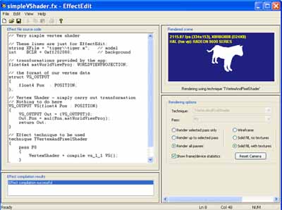
This shader (contained in an effect file) can be downloaded here: SimpleVShader.fx. You can load it into the DirectX SDK provided utility Effect Edit. You will see the effect file code to the left with the vertex shader and to the right the effect of the shader applied to a model of a tiger as below. You can edit the shader and see the changes straight away in the view window.
// transformations provided by the app, constant Uniform data
float4x4 matWorldViewProj: WORLDVIEWPROJECTION;
// the format of our vertex data
struct VS_OUTPUT
{
float4 Pos : POSITION;
};
// Simple Vertex Shader - carry out transformation
VS_OUTPUT VS(float4 Pos : POSITION)
{
VS_OUTPUT Out = (VS_OUTPUT)0;
Out.Pos = mul(Pos,matWorldViewProj);
return Out;
}
The first line defines a Uniform input MatWorldViewProj, in this case it is a matrix so it uses the float4x4 type which has 4 times 4 floats. When transforming a vertex from model space into view space we need to transform it by the world matrix, then the view matrix and finally the projection matrix (for more details on 3D transformation see this page: Matrix). We could pass each of these matrix into our vertex shader and calculate the transform by multiplying them altogether, however in this case it is easier to calculate them in our game first and then pass in the result. The WORLDVIEWPROJECTION semantic is used to tell the Effect Edit program what the constant is so it can fill it in for testing purposes outside of our application.
As mentioned before Vertex Shaders take one vertex as input, modify it in some way and then output it back into the pipeline. We need to specify the output of our shader, we do this by defining the VS_OUTPUT structure (in this case it just holds a 3D position). We use the POSITION semantic to specify to the compiler that this varying data is to be held in the correct register for a position type. Other types are PSIZE, FOG, COLORn and TEXCOORDn.
Next we write our vertex shader. We must specify the output and any input parameters. We say we will output a VS_OUTPUT structure and we will take as input a POSITION.
The next line declares an Out variable of type VS_OUTPUT and initialises its members to 0. We then calculate the transformed position by multiplying the input position by the world * view * projection matrix (passed in as a constant matWorldViewProj) using the shader call mul. Finally we return this value. A very simple shader indeed.
Vertex Shader Example 2 - Fluttering Flag
This example shows how to manipulate the vertex position data to create the effect of a fluttering flag. You can download the effect file along with a basic flag model and texture here: VShader3.zip.
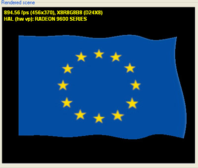
In this example we are manipulating just the vertex position to give the impression of a fluttering flag. For this to work we need some continuously changing input to use as an angle into a sin function. I have chosen to use time as this is provided by the Effect Edit program. You could of course use any variable you want and calculate it outside of the shader and pass it in as a constant.
The first part of the effect file declares some Uniform global variables and links them to the Effect Edit program via the semantics. e.g. float4x4 matWorld : WORLD; declares a variable called matWorld and tells effect edit that it should set it to the world matrix (when we use this in our game we will set it via: dxEffect->SetMatrix("matWorld",&mat))).
We want the shader to output a transformed vertex position and a texture co-ordinate so we define our output structure accordingly:
struct VS_OUTPUT
{
float4 Pos : POSITION;
float2 tex : TEXCOORD0;
};
Our shader will take as input the untransformed position and texture co-ordinate (we will simply pass the texture co-ordinate through and not alter it).
VS_OUTPUT VS(float4 Pos : POSITION,float2 tex : TEXCOORD0)
Now we need an angle to feed into our sin function so we will use the modulus operator % to give us an angle from 0 to 360:
float angle=(time%360)*2;
In the example I have scaled the value a bit just to make the flag flutter faster - you can try different values in here to see what effect you get. You could even pass the constant as a flutter speed variable into the shader.
The 3D model is defined as a flat mesh on the x,y plane. Z is pointing into the screen so to make the flag move in and out we need to alter this z value. The first step is to alter it based on the x position of the vertex and the sin of the angle:
Pos.z = sin( Pos.x+angle);
This gives a wave effect along the flag:
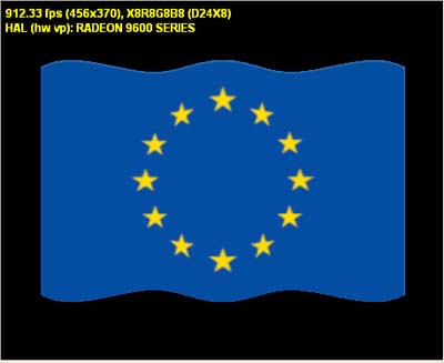
This is OK but we only get a waving effect horizontally, it would be nice to make it wave differently dependant on the y position of the vertex:
Pos.z += sin( Pos.y/2+angle);
The division by 2 is just a scaling amount, again you can try different values here to alter the effect.
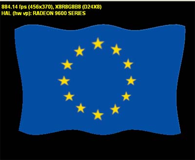
That is better, it is starting to look more realistic. However it could be improved if it looked as if the left edge were attached to a flag pole. So we should scale the wave effect dependant on how far in the x direction the vertex is:
Pos.z *= Pos.x * 0.09f;
Again, try playing with the scaling factor and seeing what happens. We now get:
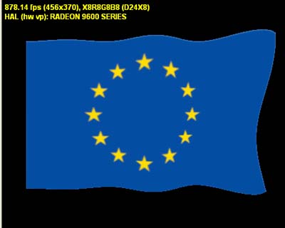
The remaining lines in the shader carry out the standard transformations and pass the texture coordinate back into the pipeline.
Vertex Shader Example 3 - Vertex Lighting
Now lets look at a slightly more complex shader. This time we will do some vertex lighting and texturing. The effect file for this example can be downloaded here: VShader2.fx.
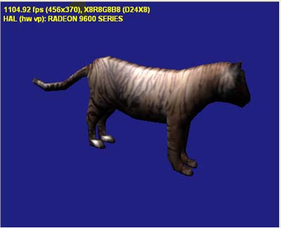
Effect edit will load the specified model, texture and manipulate the light direction (you can click and move the light arrow in the view window to change this). We are going to calculate lighting so we also need to declare and initialise some variables for the light values. We store these in the float4 type as we need values for red, green, blue and alpha.
// light intensity
float4 I_a = { 0.1f, 0.1f, 0.1f, 0.1f }; // ambient
float4 I_d = { 1.0f, 1.0f, 1.0f, 1.0f }; // diffuse
float4 I_s = { 1.0f, 1.0f, 1.0f, 1.0f }; // specular
We also need to define how the triangle will reflect this light so we provide some variables describing the material properties:
// material reflectivity
float4 k_a : MATERIALAMBIENT = { 1.0f, 1.0f, 1.0f, 1.0f }; // ambient
float4 k_d : MATERIALDIFFUSE = { 1.0f, 1.0f, 1.0f, 1.0f }; // diffuse
float4 k_s : MATERIALSPECULAR= { 1.0f, 1.0f, 1.0f, 1.0f }; // specular
float n : MATERIALPOWER = 32.0f; // power
Now on to the shader. We need to define the output of this shader and would like to output a transformed position and calculated diffuse and specular colours. We will also output a texture co-ordinate.
struct VS_OUTPUT
{
float4 Pos : POSITION;
float4 Diff : COLOR0;
float4 Spec : COLOR1;
float2 Tex : TEXCOORD0;
};
This shader will require as input the untransformed vertex position, a vertex normal so we can calculate our lighting and a texture co-ordinate (again we will do nothing to the texture co-ordinate apart from simply pass it to the output):
VS_OUTPUT VS(
float3 Pos : POSITION,
float3 Norm : NORMAL,
float2 Tex : TEXCOORD0)
As before we create an instance of our output structure and initialise it to 0. Unlike the last example we have not passed in the combined world, view and projection matrix but have passed them in separately. The next two lines calculate the position transform in view space:
float4x4 WorldView = mul(World, View);
float3 P=mul(float4(Pos, 1), (float4x3)WorldView); // position (view space)
Describing the mathematics of the lighting equation is beyond the scope of these notes, there is plenty elsewhere on these calculations (see Implementing Lighting Models with HLSL). I will also discuss the lighting equations more when looking at Pixel Shaders. What I do want to describe here is the new shader functionality in these lines of code:
float3 N = normalize(mul(Norm, (float3x3)WorldView)); // normal (view space)
float3 R = normalize(2 * dot(N, L) * N - L); // reflection vector
float3 V = -normalize(P); // view direction
Out.Pos = mul(float4(P, 1), Projection); // position (projected)
Out.Diff = I_a * k_a + I_d * k_d * max(0, dot(N, L)); // diffuse + ambient
Out.Spec = I_s * k_s * pow(max(0, dot(R, V)), n/4); // specular
We would like to calculate our lighting in View space. N is the normal vector transformed into view space. R is the reflection vector also transformed into view space. Normalize is a function to calculate the normal version of a vector. dot calculates the dot product of two vectors (beware the order).
The last three lines fill in the output values, firstly the position is transformed from view space into projection space. Next the diffuse colour is calculated as the sum of the ambient and diffuse colour components. Ambient does not depend on the direction of the light or the surface and so is simply intensity times colour. Diffuse is based on the Lambert model and is intensity * colour scaled by the angle of the vertex to the light. The scaling value is determined using the dot product. Finally specular colour is calculated. pow(x,y) returns x to the power y.
Summary
- We can write a vertex shader that will be inserted into the graphics pipeline and run on the graphics card itself.
- The shader takes vertex data as input and can manipulate this data before outputting it back into the graphics pipeline.
- The vertex shader works on one vertex at a time.
- We can alter any of the vertex data as we wish. Since we are replacing the transformation stage of the pipeline we normally have to at least transform the model position into view space.
- We can define uniform data that will be held in the shader's constant registers and can be set via our application before the shader is executed. We can also specify varying data like the vertex position, colour etc. but we must remember to specify a semantic that tells the compiler the usage of this data.
Hopefully these notes have given you an introduction to using and programming vertex shaders. There is much more you can do with them and again for further reading I would recommend the book Programming Vertex and Pixel Shaders by Wolfgang Engel (details on the Resources page).
Once the vertex data is back in the pipeline in passes through the culling stage, the triangle setup and rasterization stages before reaching the pixel shading stage. We can write shader code to be inserted into the pipeline here as well and this code is known as a Pixel Shader. The next page describes these shaders: Pixel Shaders
© 2004-2016 Keith Ditchburn
