Collisions
Handling collisions between world objects is obviously essential to computer games. Collision calculations can take time however so how accurate you make your collision detection will depend on your game type. If you are looking for very accurate physics you will want to carry out ray collision tests against all the triangles that make up your world, however for most cases you can get away with much less accurate tests. Bounding spheres and bounding boxes described below are a rather crude collision mechanism but are often all you need. Even if you do require more accurate collisions you will still use bounding shapes to allow you to reject whole objects before going down to the triangle level i.e. you want to avoid as many ray-triangle tests as possible so a first pass bounding box test will eliminate many triangles.
There is a demo to accompany these notes: BoundingBoxesDemo.zip
Note: for collisions between objects in your world you can use bounding boxes but for collisions with terrain this will not work, instead you need to determine the height at a point over the terrain, for more details look at the terrain notes.
Bounding Box Collisions
Bounding boxes and bounding spheres can be used to find collisions between objects. They are fairly simple to calculate and the cost of carrying out the collision detection is relatively cheap. Note: there are other bounding volumes that can be used.
Bounding Box
A bounding box is simply a box that encloses all the geometry of a 3D object. We can easily calculate one from a set of vertex by simply looping through all the vertices finding the smallest and biggest x, y and z values. This gives us the bottom near left co-ordinate and the top far right co-ordinate. Call these minBounds and maxBounds.
Direct3D provides a function that calculates the bounding box for you:
D3DXComputeBoundingBox(...)
This takes a vertex buffer, number of vertices and a byte size for your FVF and returns min and max bounds. A complete example using a mesh is shown below:
BYTE* pVertices=NULL;
hr=m_mesh->LockVertexBuffer(D3DLOCK_READONLY, (LPVOID*)&pVertices);
if (FAILED(hr))
return FALSE;
D3DXVECTOR3 minBounds,maxBounds;
D3DXComputeBoundingBox((D3DXVECTOR3*)pVertices, m_mesh->GetNumVertices(), D3DXGetFVFVertexSize(m_mesh->GetFVF()), &minBounds, &maxBounds);
m_mesh->UnlockVertexBuffer();
The only new part of the above is the function D3DXGetFVFVertexSize, this is required because you need to tell the function how many bytes there are between each vertex (the stride), this is dependant on your custom vertex structure size.
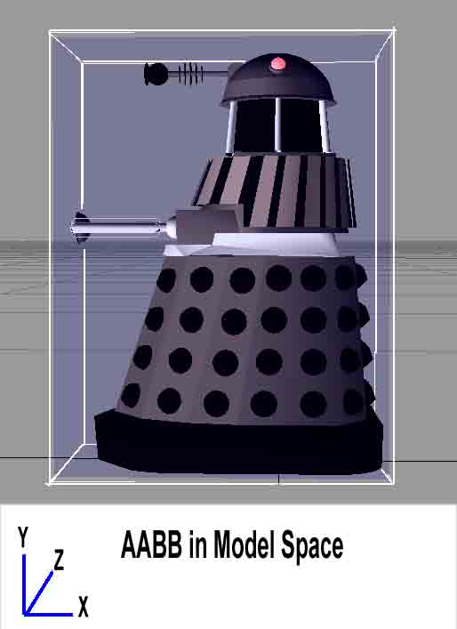
So after calculating your min and max bounds manually or via the above method you have all you need to describe your model bounding box. Since this box is calculated in model space it is known as an axis aligned bounding box in model space. An example is shown below.

Bounding Sphere
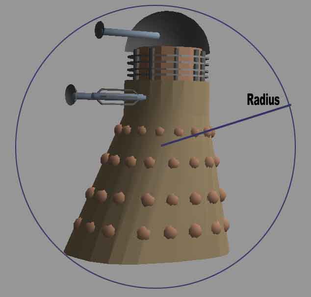
As you can see the bounding box is quite a good fit for a Dalek although the bottom being wider than the top means collisions with the head of the Dalek based solely on a bounding box would appear to happen without actually touching. Another method would be to use a bounding sphere, a bounding sphere makes it much simpler to calculate collisions as it just defines a centre point and a radius. To determine if a collision has occurred between two objects with bounding spheres we can simply find the distance between their centres and see if this is less than the sum of their bounding sphere radius.

As you can see this is also not a very good fit and for ground based collisions may actually be worse than using bounding boxes (in the case of this Dalek). So the best choice of bounding shape is dependant on the original shape, if the original shape is box like then a box may be the best fit, if it is a ball then obviously a bounding sphere is a better fit. Also sphere collision detection is less costly than bounding box detection. Direct3D again provides a function to calculate the sphere for you from a set of vertices:
D3DXComputeBoundingSphere(...)
Look in the DirectX help file for more information on this function. From now on I will talk only about bounding box collisions.
Daleks in Space
We have a bounding box defined by two 3D points: minBounds and maxBounds. This is defined in object space but when we come to check for collisions in our game we want to check for collisions in world space. From earlier notes you know that world space is created by specifying a world matrix for each entity drawn, this allows you to position and orientate the entity in your game world. We could transform all our Dalek vertices into world space and then do a bounding box calculation on the transformed vertices to get a bounding box in world space but this would be really painful and slow. Much better would be to transform the bounding box points instead, using the entities world matrix.
Oriented Bounding Box (OBB)
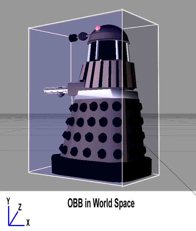
When we transform our entity into world space we may translate it, rotate it or scale it. These can cause the entity to become unaligned with the axis and our simple method of storing minimum and maximum bounds no longer works, instead we need to store a position for each of the 8 corners of the bounding box. We calculate these 8 points in object space and then transform them by the world matrix to create an OBB in world space:
// We have min and max values, use these to get the 8 corners of the bounding box
m_objectBounds[0] = D3DXVECTOR3( minBounds.x, minBounds.y, minBounds.z ); // xyz
m_objectBounds[1] = D3DXVECTOR3( maxBounds.x, minBounds.y, minBounds.z ); // Xyz
m_objectBounds[2] = D3DXVECTOR3( minBounds.x, maxBounds.y, minBounds.z ); // xYz
m_objectBounds[3] = D3DXVECTOR3( maxBounds.x, maxBounds.y, minBounds.z ); // XYz
m_objectBounds[4] = D3DXVECTOR3( minBounds.x, minBounds.y, maxBounds.z ); // xyZ
m_objectBounds[5] = D3DXVECTOR3( maxBounds.x, minBounds.y, maxBounds.z ); // XyZ
m_objectBounds[6] = D3DXVECTOR3( minBounds.x, maxBounds.y, maxBounds.z ); // xYZ
m_objectBounds[7] = D3DXVECTOR3( maxBounds.x, maxBounds.y, maxBounds.z ); // XYZ
We now have the 8 corners of our bounding box in model space.
Note: this bounding box data can be calculated just once when you first load / initialise your graphic entity and held as a member variable array in your class.
When we need to check for collisions we transform the 8 corners of the bounding box by the world matrix. In Direct3D we can use the D3DXVec3TransformCoord(...) function e.g.
// Transform the 8 corners of our object space bounding box into world space
D3DXVECTOR3 worldBounds[8];
for( int i = 0; i < 8; i++ )
D3DXVec3TransformCoord( &worldBounds[i], &m_objectBounds[i], &matWorld );

Above is an example of the Dalek rotated into world space. You can see now that we need to hold all 8 transformed corners in order to describe this Oriented Bounding Box (OBB)
Axis Aligned Bounding Box (AABB) in World Space
We now know how to create a bounding box and transform it into world space. To handle collisions we need to check if another objects bounding box has intersected the Daleks bounding box. With the above 8 corners this would involve some rather complex plane calculations so we can simplify the process even more (at the loss of some accuracy) by converting the 8 point oriented bounding box into a world axis aligned bounding box. This is simple, we just look through the 8 points for the min and max:
/*********************************************************************************
Desc: Given the 8 corners of a OBB bounding box in world space, create a AABB bounding box in world space
*********************************************************************************/
void CalcAABBFromOBB(const D3DXVECTOR3 *obb,D3DXVECTOR3 *minB,D3DXVECTOR3 *maxB)
{
assert(minB);
assert(maxB);
assert(obb);
minB->x=maxB->x=obb[0].x;
minB->y=maxB->y=obb[0].y;
minB->z=maxB->z=obb[0].z;
for (int i=1;i<8;i++)
{
if (obb[i].x < minB->x) minB->x=obb[i].x;
if (obb[i].x > maxB->x) maxB->x=obb[i].x;
if (obb[i].y < minB->y) minB->y=obb[i].y;
if (obb[i].y > maxB->y) maxB->y=obb[i].y;
if (obb[i].z < minB->z) minB->z=obb[i].z;
if (obb[i].z > maxB->z) maxB->z=obb[i].z;
}
}
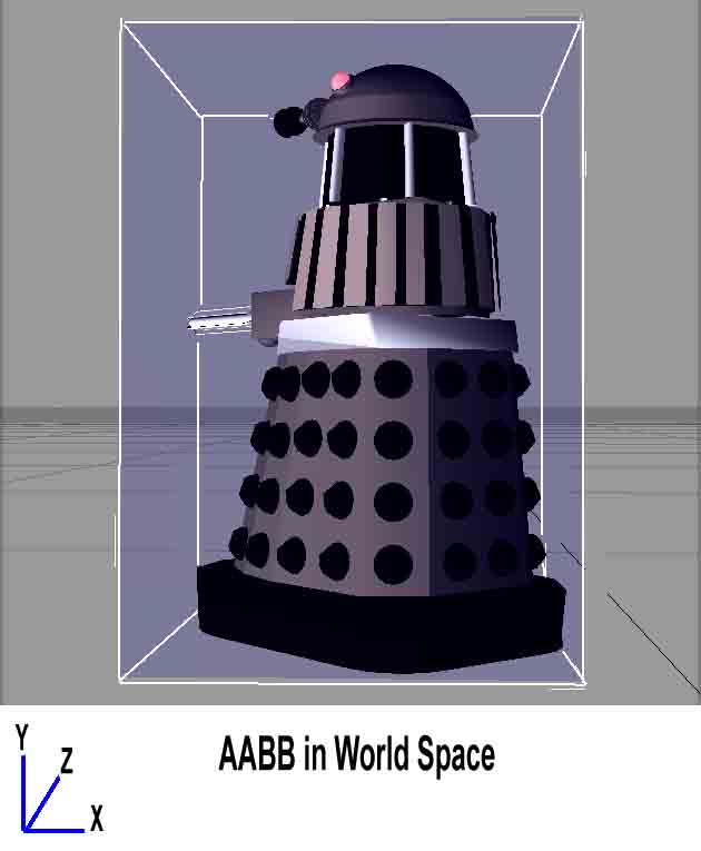
Our new bounding box therefore looks like this:

As you can see there is now quite a poor fit but handling collisions between objects is now very quick and easy. If you think about the use of a Dalek in a game as well it will often collide with its base which fits best of all.
Detecting a Collision Between two AABB
This is now very simple. Given world object A and another object B we can test for a collision simply by doing a number of checks e.g.
- If the max x position of A is less than the min x position of B they do not collide
- If the min x position of A is greater than the max x position of B they do not collide
- and the same goes for y and z
If none of the checks find that no collision occurred then obviously a collision did occur. This does make sense - read it slowly :)
Advanced Notes On Collisions
Often when creating a 3D model a games artist may also create a bounding box in their modelling package. This allows them to position it better for actual use in a particular game. In this case no code would be written to calculate the bounding box it would simply be loaded along with the geometry. Sometimes artists may create a few bounding boxes for the same model, so the Dalek may have one for its lower body and another for its head, this helps create a better fit.
When more complex collisions at the triangle level are required artists often create two versions of the model, the one you see with loads of detailed geometry and another one that you never see that is used solely for collisions. This one will be a much simpler mesh object with far less triangles to help speed up the calculations. This is also needed for network gaming because due to different PC speeds and capabilities 3D model mesh densities are often different on two players machines e.g. if you are running a high spec PC you may get detailed geometry with loads of triangles but if you are running a low spec machine a less detailed mesh object may be used. So which one would be used for collisions? It has to be fair and look right for each network player. So often a third model is used for all collisions, one that is never seen. This makes collisions consistent across all machines on the game network.
Further Reading
- For collisions with terrain see the terrain page
- For more detail on bounding box collisions see: When Two Hearts Collide: Axis Aligned Bounding Boxes
- For more information on intersection tests see this good article on Gamasutra: Simple Intersection Tests For Games
- For a nice table of object intersections and where to look them up see this site: 3D Object Intersection
- The resources page lists some good general games books
© 2004-2016 Keith Ditchburn
