XNA Terrain
Introduction
Terrain can be modelled in a number of different ways, the method described here is to create a regular grid from cells. Each cell has two triangles and 4 shared vertices:
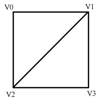

As you can see from above each cell is made from 4 vertices. We divide this into two triangles. The first uses vertices 0,1 and 2 while the second uses vertices 1,3 and 2. Remember in XNA the vertices must be defined in clockwise order.
Each vertex will have position, normal and texture co-ordinates. We want the triangles to share the vertices and therefore share the normal. With correctly created normals this will create a nice Gouraud shaded terrain. More on normal creation in a minute.
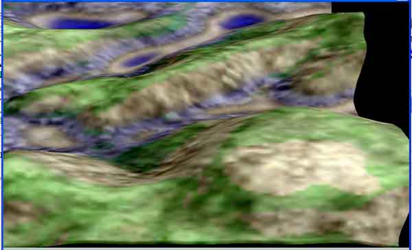
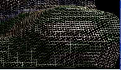
Here is a picture of a textured terrain and then below it the bottom right section of the same view in wire frame mode showing the grid cell structure:
Creating the Mesh
We will need to decide in advance how many grid cells across and down we require. Obviously the more cells the greater the detail of the mesh but we end up using more triangles and vertices. It is a trade off in quality versus performance.
To determine how many triangles we will need we can look at a very simple case of a 4 by 4 cell terrain mesh:
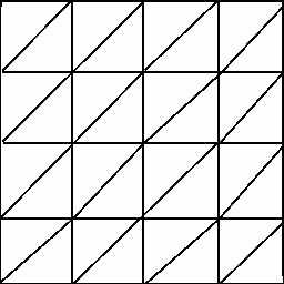
You can see we have 4 cells across (+X) and 4 down (+Z). Each row has 2 times the number of triangles as it has cells. We have number of cells + 1 vertices across. So the number of triangles is numCellsWide*2*numCellsHigh. The number of vertices is (numCellsWide+1)*(numCellsHigh+1). For the above example we therefore will have 32 triangles and 25 vertices.
If we had a larger mesh say 32 by 32 cells we would have 2048 triangles and 1089 vertices so you can see how the amount of required data can grow.
To create the above mesh we will need to have two loops x and z. We will fill in the vertices first into a vertex array (if we want lighting and to use a texture we can use the VertexPositionNormalTexture type) and then calculate the triangles. The vertices creation is easy enough you simply increment x each time until the end of the row, then reset x and increment z and repeat until they are all done. Each time you fill in the vertices x and z values. The y value is set to a height, it would be 0 for a flat terrain, more on this later.
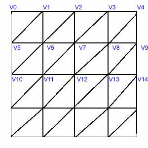
Triangle creation is more difficult. From the picture you can see that the first triangle will use vertices 0,1 and 5. The second triangle in a cell will use vertices 1,6 and 5. The picture below shows this for the first few rows of the above mesh:

Vertex Heights (y value)
The heights of your vertex points determine the hilliness of your terrain. There are many ways to create these heights, the simplest being the use of a random number. A more advanced method is to use a heightmap. A heightmap is a bitmap where the colour values are grayscale values that represent the height at each point. So you could have a 4 pixel by 4 pixel bitmap with varying grey colours to use to assign heights to the above mesh. A white colour would be a maximum height and a black colour the lowest height. This method has historically been used in the creation of golf games, flight simulators etc. Other methods include procedural creation and methods involving simulating the effect of water on a surface.
Normals
If your mesh is not flat you have to create correct normals for each of the vertex (otherwise they are all 0,1,0 - pointing straight up). These normals will be used automatically by XNA in the lighting calculations to create a curved look to the terrain. To create these normals you have to take the average of all the triangle normals that connect to the vertex.
So in the above image to calculate the normal for V6 you would need first to calculate the triangle normal of the connecting triangles (ones that share this vertex), there are 6 of them altogether. We add up all these triangle normals and then divide by 6 to get the average normal which is then assigned to the vertex. The calculation of these normals can be done after creating your vertex and triangle indices. Note that if every triangle is the same size you do not actually have to divide by 6 but can simply normalise the result.
The simplest way to calculate the vertex normals is to follow these steps
- Set all vertex normals to 0,0,0
- For each triangle
- Calculate the triangle normal by making two vectors from two sides of the triangle and doing a cross product on them
- Add this normal to each of the the three vertex normals that make up that triangle
- Normalise all vertex normals
Advanced note: if your mesh were not a regular grid as described here, for best results you would need to weight the affect of each connecting triangles' normal by the relative size of that triangle.
Texture Co-ordinates
For any texture the UV co-ordinates are 0,0 for top left and 1,1 for bottom right. If you go beyond 1 it causes the texture to be repeated. For your terrain you could use just one texture and make the top left vertex have X=0 and Y=0 and the bottom right vertex have X=1 and Y=1. For vertices in-between you will need to assign a fractional amount.
A Practical Example
In this next section I will describe a more detailed way of implementing the terrain using the above techniques. Note that there are a number of ways to go about doing this. If you get lost I find it useful to use paper to draw a simple mesh and label vertices etc. It can be tricky to visualise otherwise.
Step 1 - Gathering the data
The first step is to think what we want to specify in advance for our terrain in terms of creation parameters and then from this derive some useful values. I think there are three useful sets of data 1) how many cells across and down we want to have and 2) how big the world is across and down 3) the filename of a texture to map onto the terrain. The first allows a caller to control the density of the mesh and the second makes the terrain the correct size for the game world. So I can image a function taking:
void CreateTerrain(int worldWidth, int worldHeight, int numCellsWide, int numCellsHigh, string textureName)
Note on height and width: when designing terrain I tend to find it easiest to think in terms of looking down on the terrain from above. This means the X axis is to the right and the Z axis downwards. It is therefore logical to think in terms of a 2D width and height grid with height being +Z.
We are going to have to create arrays to hold our vertex data and triangle indices so we need to add those to our class and then calculate how big they need to be, I would add to the class member variables like so:
VertexPositionNormalTexture[] m_vertices;
int[] m_indices;
Then in the CreateTerrain function calculate how many we will need. From the sections above we saw how to calculate the various values based on our grid. I tend to assign these to variables at the start of the function so they can be used throughout. Unused ones can just be deleted later on.
Number of vertices wide will be numCellsWide+1 and number of vertices high will be numCellsHigh+1 - I name these numVerticesWide and numVerticesHigh. Total vertices is therefore:
m_numVertices = numVerticesWide * numVerticesHigh;
Number of triangles wide will be numCellsWide * 2 as there are two triangles to a cell. Number of triangles high will be simply numCellsHigh. I name these accordingly and can then calculate the number of triangles:
m_numTriangles = numTrianglesWide * numTrianglesHigh;
We can now create our arrays. Remember that the index array has 3 indices per triangle so we need to multiply that in:
m_indices = new int[m_numTriangles * 3];
m_vertices = new VertexPositionNormalTexture[m_numVertices];
We also need to take into account the size of the world. Normally we put the centre of the world at 0,0,0 so we need to stretch our world from -worldWidth / 2 to + worldWidth /2 in the X axis and -worldHeight / 2 to + worldHeight /2 in the Z axis.
Step 2 - Creating the vertices
To create our vertices we can loop along X and down Z in our grid, here is that image again:


As we loop we fill in our vertex data so we will need to have a world X and Z position, a normal (for lighting to work correctly) and texture co-ordinates. For the purpose of this example I will assume a flat terrain with Y value of 0 and hence a normal pointing straight up (0,1,0). For the texture co-ordinates I will assume we want to map the texture across the whole terrain.
The approach I use is to have a variable for the world x position and for the world z position and increment them as we go through. Taking all this into account here is a typical loop:
// Fill in the vertices
int count = 0;
int worldZPosition = startZPosition;
for (int y = 0; y < numVerticesHigh; y++)
{
int worldXPosition = startXPosition;
for (int x = 0; x < numVerticesWide; x++)
{
m_vertices[count].Position = new Vector3(worldXPosition, 0, worldZPosition);
m_vertices[count].Normal = Vector3.Up;
m_vertices[count].TextureCoordinate.X = (float)x / (numVerticesWide - 1);
m_vertices[count].TextureCoordinate.Y = (float)y / (numVerticesHigh - 1);
count++;
// Advance in x
worldXPosition += cellXSize;
}
// Advance in z
worldZPosition += cellYSize;
}
Please don't just cut and paste the above but make sure you understand it. By understanding it you will be able to fix any bugs in your code and create your own terrain again in the future!
Step 3 - Creating the triangles
Triangle creation is a bit more difficult. We need to fill our index buffer which is made up of 3 integers per triangle. Each integer is an index into the vertex buffer. We need to come up with a generic way of doing this irrespective of the size of our terrain grid. I find it best to draw a 4 by 4 grid and write down the required values and then derive an equation based on cells wide and high that will work in any situation.
Looking at the previous example diagram you can see the first cell will have two triangles. The first triangle is made from vertices with indices 0,1 and 5 and the second from 1,6 and 5. The diagram has 4 cells wide by 4 high so from that we can see that the first triangle is made from: first vertex, first vertex +1, first vertex + numVerticesWide. The second is first vertex +1, first vertex + numVerticesWide +1, first vertex + numVerticesWide. Here I am assuming first vertex is the index of the first vertex in the cell.
We need to keep variables for the current index buffer index and the first vertex in the cell and then loop through all the cells. The only slight complication is that we do not create a cell beginning with the last vertex on a row so we need to advance the first vertex variable twice at the end of a row. Below is some example code to create the triangles:
int index = 0;
int startVertex = 0;
for (int cellY = 0; cellY < numCellsHigh; cellY++)
{
for (int cellX = 0; cellX < numCellsWide; cellX++)
{
m_indices[index] = startVertex + 0;
m_indices[index + 1] = startVertex + 1;
m_indices[index + 2] = startVertex + numVerticesWide;
index += 3;
m_indices[index] = startVertex + 1;
m_indices[index + 1] = startVertex + numVerticesWide + 1;
m_indices[index + 2] = startVertex + numVerticesWide;
index += 3;
startVertex++;
}
startVertex++;
}
Step 4 - Drawing the terrain
To draw the terrain we will need to use an XNA drawing method that allows us to provide indices. Below I am using DrawUserIndexedPrimitives. Also bear in mind you will need to create an effect before drawing (fill in it's attributes for texture and the matrices) and set the vertex declaration on the XNA device (see Simple Triangle for more information).
m_effect.Begin();
foreach (EffectPass pass in m_effect.CurrentTechnique.Passes)
{
pass.Begin();
device.DrawUserIndexedPrimitives(PrimitiveType.TriangleList, m_vertices,
0, m_vertices.Length, m_indices, 0, m_indices.Length / 3);
pass.End();
}
m_effect.End();
Further Work
The above creates a textured flat terrain to any size and to any density. Obviously a flat terrain is quite boring and you could just as well draw it with a quad however you now have the basis on which to build. You could try setting the vertex Y value to a random value to create hills, or apply a function or source the heights from a graphic where the colours represent heights (known as a height map). Remember though that once you change the heights you will also need to change the vertex normals so that the lighting works correctly.
Collisions
Collision with terrain is done quite differently to collisions between objects. Bounding boxes will not work in this case. We could cast a ray and carry out ray triangle collisions tests or if we just want to position things on the terrain we could find the height at a point. Since we are using a regular grid (above) finding the correct grid cell that a collision has occurred in is actually quite simple. We just use the position offset into the grid and divide by the cell size to determine the index of the correct cell. Once we have the cell we could calculate a rough height from the nearest vertex or use an average of the cell vertices but for complete accuracy we need to determine the triangle in the cell that is collided with and then calculate the height in that triangle. Notes on this will follow at a later date.
Advanced note: for very large mesh you can split the mesh up and use different level of detail (LOD) depending on the distance from the camera. Note though that stitching issues between different mesh with different LOD can be an issue. For a good discussion of these methods take a look at the book Real Time 3D terrain Engines by Greg Snook (details on the resources page).
Further Reading
- If you are interested in rendering terrain in real time with real time calculation of textures Greg Snook's book 'Real Time Terrain Generation ...' is very good. It must be good as it has a version of my T2 program on it :). You can find details on the Resources page.
- Programs for generating terrain and textures include FreeWorld3D,the popular Terragen and my T2 program.
© 2004-2016 Keith Ditchburn

